12v Ignition Switch Wiring Diagram! (Learn How To Wire!)

Author:

12v Ignition Switch Wiring Diagram

Affiliate Disclaimer

As an affiliate, we may earn a commission from qualifying purchases. We get commissions for purchases made through links on this website from Amazon and other third parties.

A 12V ignition switch wiring diagram is a useful tool for understanding how the electrical components in your vehicle’s ignition system are connected.

If you’ve ever wondered about the intricacies of this crucial part, you’re in the right place.

In this article, we will provide a simple and concise explanation of what a 12V ignition switch wiring diagram is and how it can help you troubleshoot any issues with your vehicle’s ignition system.

So, let’s dive in and unravel the mysteries behind this essential automotive component!

What Is a 12v Ignition Switch?

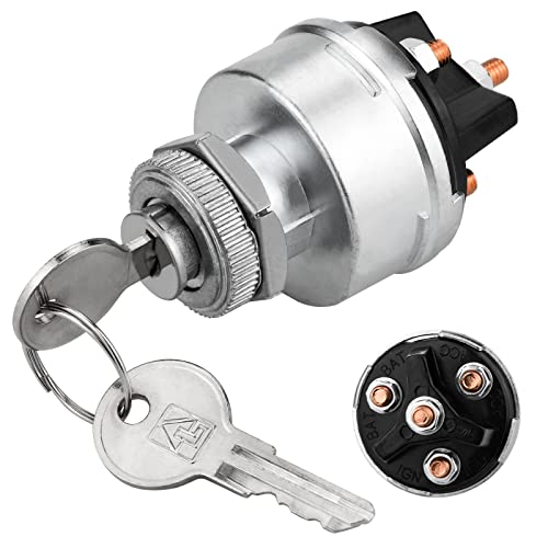
A 12V ignition switch is a switch that controls the flow of electricity to the ignition system of a vehicle. It is typically located on the steering column and has three or four positions:

  • OFF: This position cuts off all power to the ignition system.
  • ACC: This position provides power to accessories such as the radio, headlights, and dashboard lights.
  • ON: This position provides power to the ignition system and allows the engine to start.
  • START: This position engages the starter motor to crank the engine.

Some ignition switches also have a fourth position, which is used for accessories such as a remote starter or alarm system.

The ignition switch is typically actuated by a key, but some vehicles have push-button ignition switches. The switch is made of a metal alloy and has several terminals that connect to the different wires in the ignition system.

When the ignition switch is turned to the ON position, it closes a circuit that allows power to flow from the battery to the ignition system. This power is then used to energize the ignition coil, which creates a spark that ignites the fuel in the engine.

Here Are Some of The Common Problems with A 12 v Ignition Switch:

  • The switch may be worn out or damaged, causing it to stick or not turn.
  • The contacts in the switch may be corroded or dirty, preventing them from making a good connection.
  • The switch may have a loose or broken wire.
  • The switch may be faulty internally.

If you experience any problems with your ignition switch, it is important to have it repaired or replaced by a qualified mechanic.

How Does A 12v Ignition Switch Work?

A 12V ignition switch works by turning a mechanical rotary switch that connects and disconnects electrical circuits in the vehicle’s ignition system. The switch is typically located on the steering column and is operated by a key.

When the key is turned to the ON position, the switch closes a circuit that allows power to flow from the battery to the ignition coil. The ignition coil then uses this power to create a spark that ignites the fuel in the engine.

The ignition switch also has a START position. When the key is turned to this position, the switch engages the starter motor, which cranks the engine.

The ignition switch is an important part of the vehicle’s ignition system and is essential for starting the engine. If the ignition switch fails, the engine will not start.

Here Is a More Detailed Explanation of How a 12 v Ignition Switch Works:

  1. The ignition switch has three or four terminals, depending on the vehicle. The terminals are typically labeled ACC, ON, START, and BAT.
  2. The ACC terminal provides power to accessories such as the radio, headlights, and dashboard lights.
  3. The ON terminal provides power to the ignition system and allows the engine to start.
  4. The START terminal engages the starter motor.
  5. The BAT terminal is connected to the battery.

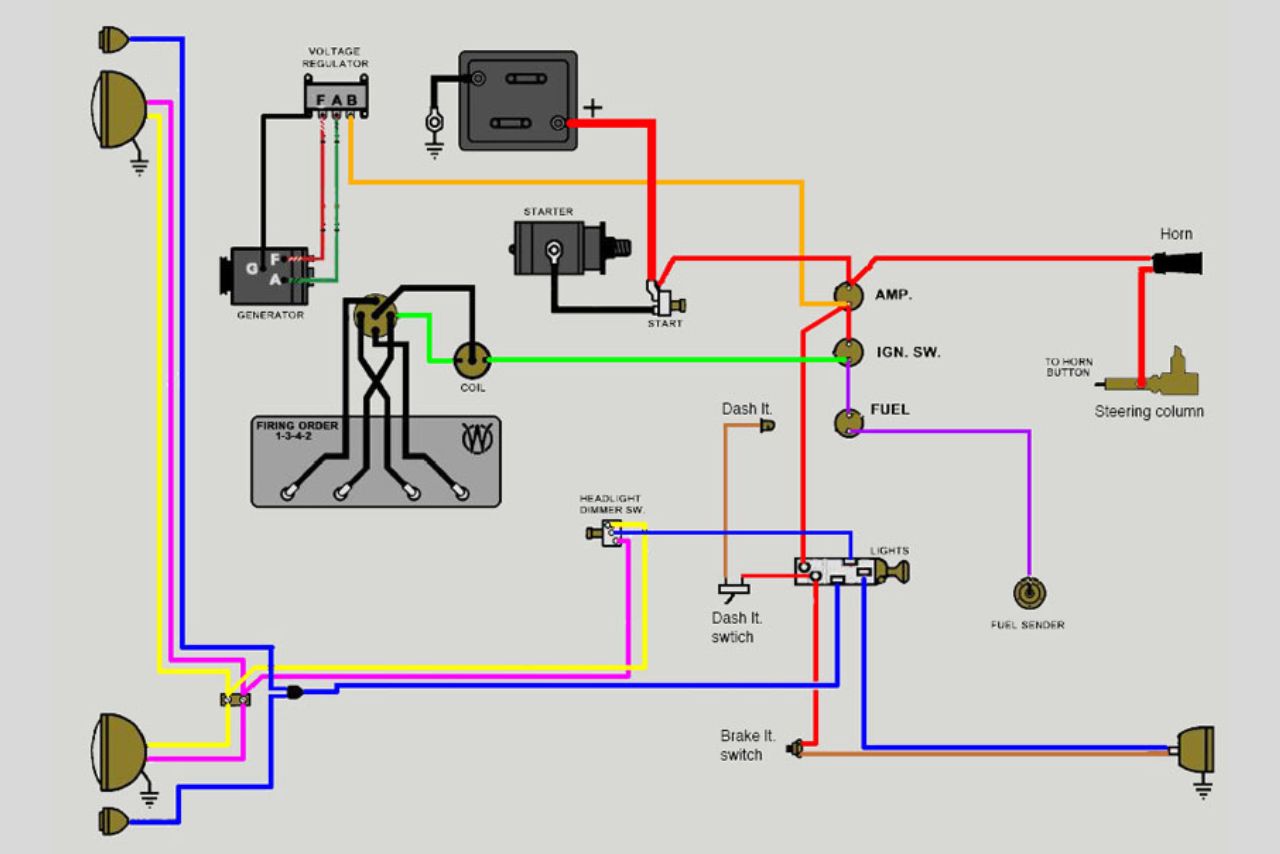
12v Ignition Switch Wiring Diagram:

12v Ignition Switch Wiring Diagram

When the key is turned to the ACC position, the switch closes the circuit between the ACC terminal and the BAT terminal. This allows power to flow from the battery to the accessories.

When the key is turned to the ON position, the switch closes the circuit between the ON terminal and the BAT terminal. This allows power to flow from the battery to the ignition system.

When the key is turned to the START position, the switch closes the circuit between the START terminal and the BAT terminal. This engages the starter motor, which cranks the engine.

Once the engine starts, the key should be turned back to the ON position. This will prevent the starter motor from running continuously and damaging itself.

The Basics of Ignition Switch Wiring:

12v Ignition Switch Wiring Diagram

When it comes to understanding ignition switch wiring, it’s essential to grasp the basics. The ignition switch plays a crucial role in starting and powering your vehicle.

It acts as a control device that allows or interrupts the flow of electrical current from the battery to various components.

To help you understand how ignition switch wiring works, let’s break down its key elements:

  1. Ignition Switch: This is where it all starts. The ignition switch is typically located on the steering column or dashboard. It has different positions such as Off, Accessory (ACC), On, and Start.
  2. Battery Connection: The ignition switch receives power from the vehicle’s battery through a designated wire known as “battery positive.” This connection ensures that there is always power available for other electrical components when needed.
  3. Accessory Position (ACC): When turned to ACC position, power flows only to certain accessories like radio or air conditioning while leaving out major engine-related systems.
  4. On Position: In this position, the ignition switch sends power to most electrical systems in your vehicle except for the starter motor circuit.
  5. Start Position: Turning your key or pushing a button activates this position which energizes both starter motor circuit and fuel system allowing your engine to start running.

It is important to note that every vehicle may have slight variations in their ignition switch wiring depending on make and model specifications.

How to Wire a 12v Ignition Switch?

12v Ignition Switch Wiring Diagram

Here is the step by step guide to wire a 12v Ignition Switch.

When it comes to wiring an ignition switch, having the right tools and materials at hand can make the process much smoother. Here are some essential items you’ll need:

Tools:

  • Wire strippers or a wire cutter/stripper combination tool
  • Electrical tape or heat shrink tubing
  • Crimping tool or soldering iron (depending on your preferred method of connection)
  • Multimeter for testing electrical connections
  • Screwdrivers (both flathead and Phillips) for removing panels and accessing wires
  • Drill with appropriate drill bits, if necessary

Materials:

  1. Ignition switch: The main component that controls the power supply to your vehicle’s electrical system.
  2. Wiring harness: Provides a set of pre-wired connectors that simplify the installation process.
  3. Electrical wires: Ensure you have different colors available to distinguish between various connections.
  4. Fuses and fuse holder: Protects your vehicle’s electrical system from overload by interrupting excessive currents.
  5. Wire connectors/terminals: Used to join multiple wires together securely.
  6. Heat shrink tubing/electrical tape: Insulates exposed wire connections to prevent short circuits or electrical hazards.
  7. Mounting brackets/hardware: Required if your ignition switch needs secure attachment.

Step-by-Step Guide: How to Wire a 12v Ignition Switch?

12v Ignition Switch Wiring Diagram
  1. Determine the wiring diagram of your specific ignition switch model. Consult the manufacturer’s manual or search online for a reliable source.
  2. Familiarize yourself with the different terminals on the ignition switch. Typical terminals include:
TerminalDescription
B+Battery positive connection
ACCAccessory power connection
IGNIgnition power connection
ST/STAStarter motor solenoid connection
  1. Disconnect the negative terminal from your vehicle’s battery to prevent any accidental electrical shorts during installation.
  2. Identify which wire connects to each terminal based on your wiring diagram.
  3. Strip about 1/4 inch of insulation from each wire end using wire strippers.
  4. Connect each wire securely to its corresponding terminal using crimp connectors or by soldering them together, ensuring proper contact and preventing loose connections that could lead to electrical issues later on.
  5. Once all wires are connected, insulate each individual connection using either electrical tape or heat shrink tubing for added protection against moisture and potential short circuits.
  6. Reconnect the negative terminal of your vehicle’s battery once you have finished wiring the ignition switch.
  7. Test your newly wired 12v ignition switch by turning it ON and OFF, checking if all functions work as intended (e.g., accessories powering up, engine starting). If any issues arise, double-check your connections and consult your wiring diagram again before making adjustments.

Common Mistakes to Avoid When Wiring an Ignition Switch:

When it comes to wiring an ignition switch for your 12v system, there are a few common mistakes that you should avoid. These mistakes can lead to electrical issues or even pose a safety risk.

To ensure a smooth and trouble-free installation, keep the following points in mind:

  1. Incorrect wire connections: One of the most common mistakes is connecting wires improperly. Make sure to double-check the wiring diagram and follow it precisely. Connecting wires incorrectly can result in short circuits or damage to your ignition switch.
  2. Using low-quality materials: Opting for cheap or substandard materials may seem like a cost-saving measure, but it can lead to problems down the line. Always use high-quality connectors, terminals, and wiring components that are suitable for automotive applications.
  3. Neglecting proper insulation: Insulation plays a crucial role in preventing electrical shorts and protecting your system from external elements such as moisture and heat. Ensure all exposed wires have adequate insulation by using quality heat shrink tubing or electrical tape.
  4. Overlooking fuse protection: Fuses act as safeguards against excessive currents that could damage your ignition switch or other components of your electrical system. Install appropriate fuses at key connection points to protect both the switch and connected devices.
  5. Failure to secure connections: Loose connections not only increase resistance but also make them vulnerable to accidental disconnections due to vibrations or vehicle movement. Use crimp connectors or solder joints (when applicable) and secure them tightly with zip ties or clamps.
  6. Skipping wire routing considerations: Properly route your wires away from moving parts, sharp edges, hot surfaces, or areas prone to water exposure whenever possible—this helps prevent potential hazards caused by chafing, cutting through wire casings, overheating, etc.
  7. Not labeling connections properly: Keep things organized by labeling each wire or connection point. This will save you time and effort during troubleshooting or future modifications.

Troubleshooting Tips for Issues with Ignition Switch Wiring:

Here are some troubleshooting tips to help you identify and resolve issues with your 12v ignition switch wiring:

  1. Check the Connections: Ensure that all connections between the ignition switch and other components are secure and properly connected.
  2. Inspect the Wiring Harness: Examine the wiring harness for any signs of damage, such as frayed wires or loose connections. If you find any issues, repair or replace the affected sections.
  3. Test Continuity: Use a multimeter to test continuity along each wire connected to the ignition switch. This will help identify any breaks in the circuit.
  4. Verify Voltage Output: Check if there is voltage output from the ignition switch when it’s turned on. Connect one probe of a voltmeter to an output terminal on the switch while grounding the other probe, then turn on the switch and measure voltage. If there is no voltage, it may indicate a faulty ignition switch.
  5. Inspect Fuses and Relays: Inspect all relevant fuses and relays related to your ignition system for signs of damage or corrosion. Replace any faulty ones accordingly.
  6. Consider Key Cylinder Issues: If you experience problems with turning or removing your key from the ignition cylinder, it could be due to worn-out tumblers or mechanical faults within the cylinder itself.
  7. Consult Wiring Diagrams: Refer to accurate wiring diagrams specific to your vehicle make and model while troubleshooting electrical issues related to your 12v ignition system.
  8. Seek Professional Help if Required: If you’re unable to diagnose or fix an issue with your 12v ignition switch wiring despite following these troubleshooting steps, consult a professional automotive electrician who can provide expert assistance.

Conclusion: 12v Ignition Switch Wiring Diagram!

Understanding the 12v ignition switch wiring diagram is essential for anyone working with automotive electrical systems.

By following the correct wiring connections and ensuring proper grounding, you can ensure a smooth and reliable ignition process for your vehicle.

Remember to always refer to the specific wiring diagram provided by your vehicle’s manufacturer or consult an expert if you encounter any difficulties during installation or troubleshooting.

Taking the time to familiarize yourself with the different components and their functions will save you time, effort, and potential costly repairs in the long run.

With this knowledge at hand, you’ll be better equipped to tackle any issues related to your vehicle’s ignition system confidently.

Whether it’s replacing a faulty switch or installing a new one, having a clear understanding of the 12v ignition switch wiring diagram empowers you to maintain optimal performance and functionality of your vehicle’s electrical system.

FAQs

Why Do I Need a 12v Ignition Switch Wiring Diagram?

A 12v ignition switch wiring diagram is necessary when you need to understand or troubleshoot the electrical system of a vehicle.
It helps you to identify the correct wires and connections for the ignition switch, which is essential for starting the engine and controlling various electrical functions in the vehicle.

How to Read a 12v Ignition Switch Wiring Diagram?

To read a 12v ignition switch wiring diagram, you should start by identifying the various symbols and labels used in the diagram.
These symbols represent different components such as batteries, fuses, switches, and wires.
Each component is usually labeled with a letter or number that corresponds to a specific terminal or connection point.

What Are the Common Components in A 12v Ignition Switch Wiring Diagram?

Common components in a 12v ignition switch wiring diagram include the ignition switch itself, starter motor, ignition coil, battery, fuse box, and various accessories such as lights, radio, and air conditioning.

Can I Modify the 12v Ignition Switch Wiring Diagram?

It is generally not recommended to modify the wiring diagram of a vehicle’s electrical system unless you have a good understanding of electrical circuits and automotive wiring.
Modifying the wiring without proper knowledge can lead to electrical problems, short circuits, and other issues.

Where Can I Find a 12v Ignition Switch Wiring Diagram for My Vehicle?

You can find a 12v ignition switch wiring diagram for your specific vehicle in the service manual or repair manual for that vehicle.
These manuals are available from automotive stores, online retailers, or directly from the vehicle manufacturer.

About the author

Latest posts