5 Pole Ignition Switch Wiring Diagram: (The Ultimate Guide!)
Author:
Jimmy Grey
Affiliate Disclaimer
As an affiliate, we may earn a commission from qualifying purchases. We get commissions for purchases made through links on this website from Amazon and other third parties.
A 5 pole ignition switch wiring diagram is a helpful visual representation of the electrical connections involved in an ignition system.
It provides a clear and concise overview, allowing you to understand how each wire should be connected for proper functionality.
Whether you’re troubleshooting an issue or installing a new ignition switch, having access to this diagram can make the process much easier.
In this article, we will explore the components of a typical 5 pole ignition switch and guide you through the wiring connections step by step. So, let’s dive in and unravel the mysteries of your vehicle’s ignition system!
Table of contents
What is a Pole Ignition Switch?
A pole ignition switch, also known as an automotive ignition switch or key switch, is a crucial component in the electrical system of a vehicle. It is responsible for controlling the power supply to various systems and accessories in your car.
Here are some key points about a pole ignition switch:
Definition: A pole ignition switch is an electrical switch that activates the starter motor and controls the flow of electrical current from the battery to other components when you turn your car’s key.
Number of Poles: The term “pole” refers to the number of separate circuits controlled by the ignition switch. In most vehicles, there are three main poles: battery (B), accessory (ACC), and start (ST). Some switches may also have additional poles for features like headlights or windshield wipers.
Battery Pole (B): This pole connects directly to your car’s battery and provides constant power supply even when the engine is off. It powers essential functions like lights, radio, clock, and other accessories.
Accessory Pole (ACC): When you turn your key one click backward from the “off” position without starting the engine, it engages this pole. It allows power flow to non-essential components such as windows, air conditioning, stereo system, etc., while preserving energy from draining out completely.
Start Pole (ST): Turning your key all the way clockwise engages this pole and activates the starter motor via a solenoid connection within it. The starter motor then cranks up your engine until it fires up successfully.
Other Poles: Some advanced ignition switches may include extra poles for specific functions like headlights or windshield wipers control.
Understanding how a pole ignition switch works can help troubleshoot any issues related to starting or powering different systems in your vehicle effectively.
5 Wire Ignition Switch Bypass:
A 5 wire ignition switch bypass is a way to start a vehicle without the ignition switch. This can be useful if the ignition switch is broken or if you have lost the key.
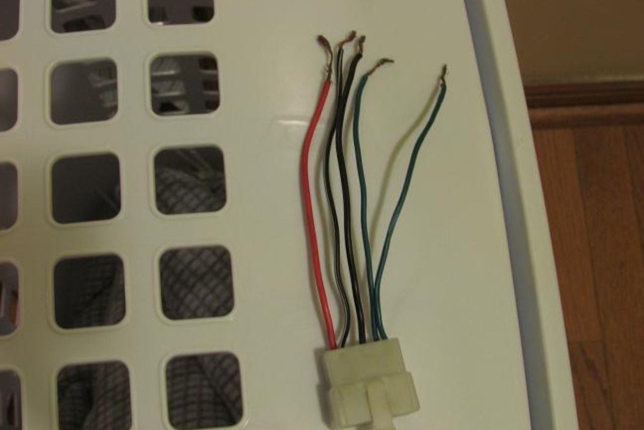
To bypass a 5 wire ignition switch, you will need to identify the 5 wires that connect to the switch. These wires are typically labeled as:
Power
Ground
Starter
ACC (accessories)
IGN (ignition)
Once you have identified the wires, you will need to connect them together in the correct order. The order of the wires will vary depending on the make and model of your vehicle. You can usually find the correct wire order in your vehicle’s owner’s manual.
Once the wires are connected, you should be able to start the vehicle by turning the key in the ignition switch. However, it is important to note that bypassing the ignition switch will disable some of the vehicle’s safety features.
For example, the airbag system may not work if the ignition switch is bypassed.
It is also important to note that bypassing the ignition switch is not a permanent solution. If the ignition switch is broken, it will need to be repaired or replaced.
Here are the steps on how to bypass a 5 wire ignition switch:
Identify the 5 wires that connect to the ignition switch.
Connect the wires together in the correct order.
Turn the key in the ignition switch.
The vehicle should start.
Be aware that bypassing the ignition switch will disable some of the vehicle’s safety features.
If the ignition switch is broken, it will need to be repaired or replaced.
How to Wire a 5 Pole Ignition Switch?
To wire a 5 pole ignition switch, you will need to identify the 5 wires that connect to the switch. These wires are typically labeled as:
Power
Ground
Starter
ACC (accessories)
IGN (ignition)
Once you have identified the wires, you will need to connect them to the correct terminals on the switch. The terminal identifications are usually printed on the switch itself.
The following is a table of the wire colors and their corresponding terminals:
Wire Color
Terminal
Red
1 (power)
Black
2 (ground)
Yellow
3 (starter)
Green
4 (ACC)
White
5 (IGN)
Once the wires are connected, you should be able to start the vehicle by turning the key in the ignition switch.
Here are the steps on how to wire a 5 pole ignition switch:
Identify the 5 wires that connect to the ignition switch.
Identify the Pins: The first thing you need to do is identify each pin on the ignition switch. A typical 5-pole ignition switch has five pins labeled as follows:
ACC: Accessory
IGN: Ignition
ST: Start
BAT: Battery
GND: Ground
Understand the functions: Each of these pins serves a specific function in your vehicle’s electrical system.
ACC (Accessory): This pin provides power to accessories such as radios, lights, or other electronic devices when the key is turned to the accessory position.
IGN (Ignition): This pin supplies power to essential engine components like spark plugs and fuel injectors while starting and running.
ST (Start): When this pin receives power, it engages the starter motor and starts cranking the engine.
BAT (Battery): The battery pin connects directly to your vehicle’s battery positive terminal and supplies constant power even when other positions are not engaged.
GND (Ground): This pin ensures proper grounding of electrical circuits.
Follow wire color codes: To decipher which wires connect to each pin, refer to a wiring diagram specific to your vehicle make and model. Different manufacturers may use different wire color codes, so be sure to consult an accurate reference.
Trace each wire connection: Once you have identified all pins on your ignition switch and their respective functions, trace each wire from its corresponding connector point in relation to those pins.
Check for continuity issues: While tracing wires, ensure that there are no breaks or loose connections that could disrupt current flow within your ignition system.
Understanding a 5-pole ignition switch wiring diagram is crucial for troubleshooting and making modifications to your vehicle’s electrical system.
Note: Always consult a professional or refer to manufacturer documentation when working with complex electrical systems.
Step-By-Step Guide to Wiring a 5-Pole Ignition Switch:
If you’re looking to wire a 5-pole ignition switch, follow these simple steps:
Gather the necessary materials:
5-pole ignition switch
Wire cutters/strippers
Electrical tape or heat shrink tubing
Crimping tool or soldering iron (optional)
Determine the type of ignition system: Before starting, make sure you understand what type of ignition system your vehicle has – whether it’s points-type, electronic, or distributorless.
Disconnect the battery: For safety purposes, always disconnect the negative terminal of your vehicle’s battery before working on any electrical components.
Identify and label wires: Familiarize yourself with the different wires in your vehicle’s wiring harness that connect to the ignition switch. Use labels or markers if needed for easier identification later on.
Remove old switch (if applicable): If you’re replacing an existing ignition switch, carefully remove it according to manufacturer instructions.
Prepare new switch: Examine your new 5-pole ignition switch and identify its terminals – typically labeled as BATT, ACC, IGN/RUN/SIG1/SIG2/PWR/START depending on manufacturer specifications.
Connect wires one by one:
Connect the “BATT” terminal: Attach this wire from your main power source (usually coming directly from the battery) to provide constant power.
Connect “ACC” terminal: This wire supplies power when in accessory mode; connect accessories like radios or interior lights here.
Connect “IGN/RUN” terminal: This wire provides power during normal engine operation; attach it to essential components like fuel pumps and engine control modules.
Connect other terminals as required based on manufacturer specifications.
Secure connections: Once all the wires are connected, secure them using crimp connectors or soldering (if preferred) to ensure proper electrical conductivity. Insulate each connection with electrical tape or heat shrink tubing.
Test the ignition switch: Reconnect your vehicle’s battery and test the newly wired 5-pole ignition switch by turning it to different positions (off, accessory, on/run). Verify that power is reaching the appropriate components at each position.
Remember, if you’re unsure about any step in this process, consult a professional automotive electrician for guidance and assistance. Safety should always be a priority when working with electrical systems in vehicles.
Common Mistakes to Avoid:
When it comes to wiring a 5 pole ignition switch, there are some common mistakes that you should avoid. By being aware of these pitfalls, you can save yourself time and frustration in the long run.
Here are some key things to keep in mind:
Not following the correct wiring diagram: One of the biggest mistakes people make is not using the right wiring diagram for their specific ignition switch model. Each switch may have different pin configurations, so it’s crucial to consult the appropriate diagram before proceeding.
Incorrect wire connections: Another mistake that often occurs is improperly connecting wires. This can lead to various issues such as short circuits or even damage to your ignition system. Always double-check your connections against the wiring diagram and ensure that each wire is securely attached.
Using inadequate gauge wire: Using wires with an inadequate gauge can cause problems down the line. It’s important to use wires that are capable of handling the electrical load required by your ignition system. Refer to a wire gauge chart or consult an expert if you’re unsure about which gauge wire to use.
Neglecting proper insulation: Proper insulation is essential when dealing with electrical connections. Failing to insulate exposed wires increases the risk of short circuits and potential hazards like fires or electrocution. Make sure all bare wires are adequately covered with suitable insulation materials.
Skipping testing and verification: After completing your wiring work, don’t forget to test and verify its functionality before reassembling everything back together. Ignoring this step could result in wasted time and effort if any connection was made incorrectly.
By avoiding these common mistakes when working on a 5 pole ignition switch wiring project, you’ll be well on your way towards achieving a successful installation without any unnecessary setbacks or complications.
Tips for troubleshooting
When it comes to troubleshooting issues with a 5 pole ignition switch wiring diagram, there are a few key tips that can help you identify and resolve any problems. Here are some helpful pointers:
Double-check your connections: Ensure that all the wires are securely connected to their respective terminals on the ignition switch. Loose or improperly connected wires can cause electrical malfunctions.
Inspect for damaged wires: Carefully examine each wire in the ignition switch circuit for any signs of damage, such as fraying, cuts, or exposed copper. Damaged wires can disrupt the flow of electricity and lead to issues.
Test voltage levels: Use a multimeter to measure the voltage at different points along the wiring diagram. This will help you determine if there is any loss of power or irregularities in the electrical system.
Consider environmental factors: Sometimes, external elements like moisture or extreme temperatures can impact the performance of an ignition switch wiring system. Check for any signs of corrosion or water damage and take appropriate measures to address them.
Consult manufacturer’s documentation: Refer to the manufacturer’s manual or technical specifications guide for detailed information about your specific 5 pole ignition switch model. It may provide additional insights into potential troubleshooting steps tailored specifically to your situation.
Seek professional assistance when needed: If you’re unable to diagnose or fix an issue with your 5 pole ignition switch wiring diagram despite following these tips, it may be time to consult a qualified electrician or automotive technician who specializes in electrical systems.
Remember that safety should always be a priority when working with electrical components! Be sure to disconnect power sources before making any adjustments and exercise caution throughout the troubleshooting process.
Conclusion: 5 Pole Ignition Switch Wiring Diagram:
Understanding the wiring diagram for a 5 pole ignition switch is crucial for anyone working on their vehicle’s electrical system. By following the correct wiring connections, you can ensure proper functionality and prevent any potential issues down the road.
The wiring diagram provides a clear visual representation of how to connect each wire to its corresponding terminal on the ignition switch.
This knowledge allows you to troubleshoot any problems that may arise and make necessary repairs or replacements with confidence.
By familiarizing yourself with this useful resource, you can save time, money, and frustration in diagnosing and resolving ignition switch-related issues efficiently.
So whether you are an experienced mechanic or a DIY enthusiast looking to tackle electrical projects in your own garage, mastering the 5 pole ignition switch wiring diagram will undoubtedly prove worthwhile.
FAQs
What is a 5 pole ignition switch?
A 5 pole ignition switch is a component used in the electrical system of a vehicle to control the flow of electricity to the ignition system and other vehicle accessories. It typically has five terminals or poles that are connected to different electrical circuits.
What are the terminals/poles in a 5 pole ignition switch?
The five terminals or poles in a 5 pole ignition switch are typically labeled as follows: B, S, I, R, and A. Each terminal is connected to specific electrical circuits in the vehicle.
What do the terminals/poles in a 5 pole ignition switch stand for?
B: Battery terminal, which is connected to the vehicle’s battery or power source. S: Start terminal, which is connected to the starter motor to crank the engine. I: Ignition terminal, which is connected to the ignition coil or ignition system. R: Accessory or Run terminal, which is connected to various accessories such as lights, radio, etc. A: Auxiliary or Accessory terminal, which is connected to additional accessories, if needed.
How to wire a 5 pole ignition switch?
The specific wiring diagram for a 5 pole ignition switch can vary depending on the vehicle make and model. It is always recommended to refer to the vehicle’s service manual or wiring diagram for accurate and specific instructions. In general, the terminals are connected as follows: B terminal: Connects to the positive terminal of the vehicle’s battery. S terminal: Connects to the starter solenoid or starter motor. I terminal: Connects to the ignition coil or ignition system. R terminal: Connects to the accessories circuit. A terminal: Connects to additional accessory circuits, if present.
What is the purpose of a 5 pole ignition switch wiring diagram?
A 5 pole ignition switch wiring diagram serves as a guide to properly connect the terminals of the ignition switch to the appropriate electrical circuits in the vehicle. It helps ensure proper functioning of the ignition system and accessories, and also aids in troubleshooting any electrical issues.