3 Wire Ignition Switch Diagram! A Comprehensive Guide!
Author:
Jimmy Grey
Affiliate Disclaimer
As an affiliate, we may earn a commission from qualifying purchases. We get commissions for purchases made through links on this website from Amazon and other third parties.
A 3 wire ignition switch diagram is a valuable tool for understanding the wiring connections of an ignition switch in a vehicle.
It provides a clear visual representation of how the three wires, typically labeled as battery, starter, and accessory, are connected to ensure proper functionality.
By following this diagram, you can easily identify which wire corresponds to each function and troubleshoot any issues that may arise with your ignition system.
In this article, we will explore the importance of a 3 wire ignition switch diagram and guide you on how to interpret it effectively. So let’s dive right in!
Table of contents
What is an Ignition Switch?
An ignition switch is a vital component of a vehicle’s electrical system. It serves as the main control to start and stop the engine, controlling power flow throughout the system.
The ignition switch acts as a gatekeeper, allowing or preventing electricity from reaching various components in the vehicle.
When you insert your key into the ignition switch and turn it, several actions are initiated that allow your car to start.
How Does a 3 Wire Ignition Switch Work?
Accessories Position: By turning the key one notch clockwise without starting the engine, you activate electrical accessories such as lights, radio, and windshield wipers.
Ignition On Position: Turning the key another notch clockwise powers up additional systems like fuel pumps and sensors while preparing for engine start-up.
Cranking Position: In this position, when you turn your key all the way clockwise against spring resistance (usually referred to as “cranking” or “start”), it activates solenoids that engage with other parts in order for the engine to crank over and ignite.
Engine Running: Once started successfully by cranking position activation, releasing the key will cause it to return automatically back to its ‘ignition on’ position while keeping critical components powered up.
It’s important to note that different vehicles may have variations in their ignition switch designs. Some modern cars use push-button starts instead of traditional keys but still function similarly behind-the-scenes with electronic switches rather than mechanical tumblers.
3 Wire Ignition Switch Bypass:
Bypassing a 3-wire ignition switch is a process that allows you to start your vehicle without using the ignition key.
This technique is often used in emergency situations when the ignition switch is not functioning properly or if the key is lost or damaged.
Here’s a step-by-step guide on how to do a 3-wire ignition switch bypass:
Safety precautions: Ensure that the vehicle is parked on a level surface and the parking brake is engaged. Also, disconnect the negative terminal of the vehicle’s battery to prevent electrical accidents.
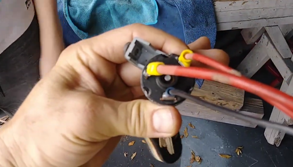
Locate the ignition switch: The ignition switch is usually located on the steering column, dashboard, or console. It is connected to a wire harness with three wires.
Identify the wires: The three wires connected to the ignition switch are typically colored red, black, and yellow. The red wire is the primary power wire, the black wire is the ground wire, and the yellow wire is the accessory power wire.
Cut and strip the wires: Using wire cutters, carefully cut the red and yellow wires close to the ignition switch. Strip about 1/2 inch of insulation from the ends of the cut wires using wire strippers.
Connect the wires: Take the stripped end of the red wire and connect it to the stripped end of the yellow wire using a wire connector or electrical tape. This connection will bypass the ignition switch and allow power to flow directly to the vehicle’s electrical system.
Ground the circuit: Take the stripped end of the black wire and connect it to a suitable ground point on the vehicle’s chassis. This will complete the circuit and provide a proper ground connection.
Test the bypass: Reconnect the negative terminal of the vehicle’s battery. Turn the key in the ignition to the “On” position. The vehicle’s electrical system should now be powered up, and you should be able to start the engine.
Restore the original wiring: If the bypass is done as a temporary solution, it’s important to restore the original wiring once the ignition switch is fixed or replaced. Cut the bypass wires and reconnect the original wires using wire connectors or electrical tape.
Remember, bypassing the ignition switch should only be done in emergency situations and with proper knowledge. If you are not sure about the process or lack experience, it’s best to consult a professional mechanic or automotive electrician for assistance.
The Importance of a Three-Wire Ignition Switch:
Enhanced Security: A three-wire ignition switch offers an added layer of security, preventing unauthorized individuals from starting your vehicle without the proper key. It ensures that only you have control over starting and operating your vehicle.
Anti-Theft Protection: With its additional wire, a three-wire ignition switch allows for the installation of anti-theft devices. These devices can deter potential thieves by immobilizing the engine or triggering an alarm system when someone tries to start the car without the correct key.
Electrical Stability: The third wire in a three-wire ignition switch is dedicated to providing a constant supply of power to essential electrical components in your vehicle. This ensures stable operation and prevents sudden loss of power while driving, which could lead to accidents or malfunctions.
Easy Replacement: In case of damage or wear, replacing a three-wire ignition switch is relatively straightforward due to its standardized wiring configuration. This makes it easier for mechanics and DIY enthusiasts alike to replace faulty switches efficiently, reducing downtime and costs associated with repairs.
What Are the Three Wires in An Ignition Switch?
Ignition Control: The primary function of a three-wire ignition switch is controlling the flow of electricity between the battery and various systems within your vehicle, such as lights, starter motor, fuel pump, etc. It serves as an interface between these systems and allows you to start or shut down your car effortlessly.
Start Position: One position on the ignition switch activates circuits necessary for starting the engine by connecting both battery power and starter solenoid wires simultaneously.
Run Position: After successfully starting the engine, switching from Start position (momentary) to the Run position allows the ignition switch to power other electrical systems in your vehicle. This includes powering the fuel pump, providing electricity to lights, and enabling accessories like radios or air conditioning.
Remember that proper installation of a three-wire ignition switch is essential for its optimal functionality. Always refer to your vehicle’s wiring diagram or consult a qualified technician when replacing or troubleshooting ignition switches.
Understanding the Wiring Diagram:
To properly understand the wiring diagram of a 3 wire ignition switch, it’s important to break it down into its components and their functions. Here are key points to help you grasp the essential elements:
Ignition Switch: The ignition switch is an electrical component that allows or interrupts the flow of electricity from the battery to various systems in your vehicle.
Battery: The battery supplies power to the ignition switch and other electrical components in your vehicle.
Start Position: When you turn the key to the start position, it completes a circuit between the battery and starter motor, allowing current to flow and enabling your engine to crank.
Accessory Position: In this position, power is supplied only to certain accessories such as radios or interior lights while preventing activation of other systems like fuel pumps or engine control modules.
Run Position: Once you release the key from start, it returns back slightly which engages a spring-loaded mechanism that keeps power flowing through circuits necessary for running your vehicle such as fuel injectors, engine sensors, and more.
Off Position: Turning off your ignition switch cuts off power supply from both accessory and run positions by breaking all connections with electrical systems except those required for safety features like airbags or hazard lights.
Wiring Connections: The wiring diagram illustrates how different wires connect various components together within your vehicle’s ignition system including switches, relays, fuses, starters motors etc., ensuring proper distribution of electric current throughout these parts when needed.
Step-by-Step Guide to Installing a Three-Wire Ignition Switch:
Installing a three-wire ignition switch can seem daunting, but with the right guidance, it can be a straightforward process. Follow this step-by-step guide to ensure a successful installation:
Gather the Necessary Tools: Before you begin, make sure you have all the tools required for the job. This may include wire cutters/strippers, electrical tape, crimping tool, and screwdrivers.
Disconnect the Battery: Safety first! Start by disconnecting the negative terminal of your vehicle’s battery to avoid any accidental electric shocks during installation.
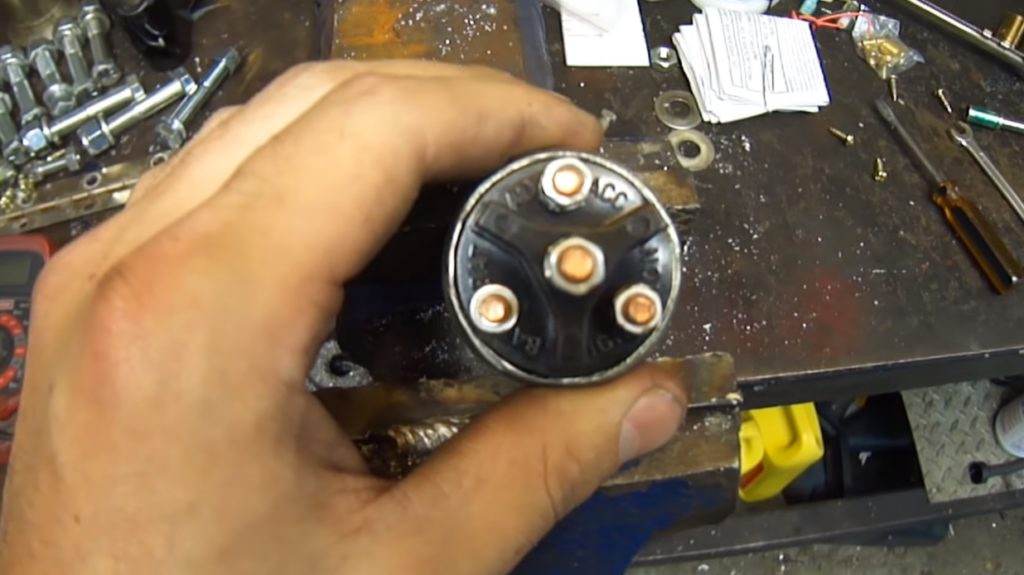
Locate Existing Wiring Harness: Find your vehicle’s existing wiring harness connected to the old ignition switch. It typically consists of three wires: power feed (constant 12V), accessory (switched 12V), and starter solenoid.
Remove Old Ignition Switch: Unscrew any mounting screws or bolts holding down the old ignition switch in place. Gently detach it from its connectors while taking note of how each wire is connected.
Prepare New Ignition Switch: Take your new three-wire ignition switch and prepare it for installation by ensuring that all connections are secure and free from dirt or debris.
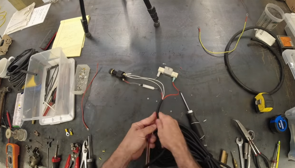
Connect Wires to New Ignition Switch: Attach each corresponding wire from your vehicle’s wiring harness to their designated terminals on the new ignition switch using either crimp connectors or soldering techniques (depending on personal preference).
Securely Mount New Ignition Switch: Once all wires are properly connected, securely mount the new ignition switch into position using screws or bolts provided with the product.
Reconnect Battery Terminal: With everything in place, reconnect your vehicle’s battery terminal by attaching the negative cable back onto its post.
Test Your Installation: Turn on your vehicle’s ignition key and verify that the new three-wire ignition switch functions correctly. Check if all accessories, such as lights and radio, are working as intended.
Double-Check Connections: Before finishing up, double-check all connections to ensure they are tight and secure. This will help prevent any issues down the road.
Common Issues and Troubleshooting Tips:
When dealing with a 3 wire ignition switch, it’s important to be aware of the common issues that can occur. Here are some troubleshooting tips to help you resolve any problems:
Ignition Switch Failure: If your ignition switch fails to turn on or off properly, it may need to be replaced. Check for any signs of damage or wear such as loose connections or a broken housing.
Electrical Shorts: A common issue with ignition switches is electrical shorts, which can cause intermittent power loss or erratic behavior. Inspect the wiring harness for any exposed wires or loose connections that may be causing a short circuit.
Key Does Not Turn: If you’re having difficulty turning the key in the ignition switch, there could be several reasons behind this problem. First, check if there is any debris caught in the keyhole and clean it if necessary. Additionally, lubricating the lock cylinder with graphite powder might help improve its functionality.
No Start Condition: When your vehicle fails to start despite turning the key in the ignition switch, there are a few things you can check for troubleshooting purposes:
Check fuel supply by inspecting fuel lines and filters.
Intermittent Power Loss: If you experience intermittent power loss while driving, it could indicate an issue with your ignition switch contacts or wiring harness connection points. Carefully examine these areas for signs of corrosion or loose terminals and clean/repair as needed.
Watch Video: 3 Wire Ignition Switch Diagram!
Conclusion: 3 Wire Ignition Switch Diagram!
Understanding the 3 wire ignition switch diagram is crucial for anyone working with automotive electrical systems. By grasping the concept of how the ignition switch functions and its role in starting a vehicle, you can troubleshoot problems effectively and ensure smooth operation.
The diagram provides a clear visual representation of the three wires involved in the ignition switch: battery power, accessory power, and starter solenoid.
Each wire has its own purpose and connects to specific components within the system. It is essential to follow this diagram correctly when installing or repairing an ignition switch to avoid any electrical mishaps.
By referencing the 3 wire ignition switch diagram, you can easily identify which wire corresponds to each function. This knowledge allows you to diagnose issues related to starting your vehicle accurately.
FAQs
How Do I Read a 3 Wire Ignition Switch Diagram?
To read a 3 wire ignition switch diagram, start by identifying the three wires: ignition, battery, and accessory. Each wire should be labeled accordingly. Then, using the diagram, trace the path of each wire to its corresponding component. Pay attention to any symbols or indicators that may be included to denote specific connections or functions.
How Do I Connect the Wires in A 3 Wire Ignition Switch Diagram?
Connecting the wires in a 3 wire ignition switch diagram involves locating the appropriate terminals or connectors on the ignition switch and the corresponding components in the vehicle’s ignition system. Use the diagram as a guide and connect the ignition wire to the ignition coil, the battery wire to the battery or main power source, and the accessory wire to the accessories you want to power.
Can I Use a 3 Wire Ignition Switch Diagram for Any Vehicle?
While the basic wiring connections in a 3 wire ignition switch diagram remain the same across most vehicles, it is essential to consult the specific wiring diagram for your vehicle’s make, model, and year. Different vehicle manufacturers may use different wire colors or configurations, so it’s crucial to ensure you have the correct diagram for your specific vehicle.